| TECHNICAL
DETAILS OF A 1MW BIOMASS GASIFIER
Gasification is a process by which solid biomass
is converted by a thermo-chemical process into
clean gaseous form in a solid Bio residue gasifier.
The process involves subjecting the solid biomass
to partial pyrolysis in sub-stoichiometric quantities
of oxygen, resulting in the formation of producer
gas, which is composed of 18% H2, 20% CO, 2%
CH4, 12 % CO2 and rest N2 and has a mean calorific
value of 4.7 MJ/Kg. The gas is then piped to
a gas engine generator, and the electricity
generated is grid synchronized for evacuation
to the State Electricity Grid.
SYSTEMS
The Power Plant shall consist of the following:
A. A. Gasification Plant.
B. B. Power Package.
C. C. Auxiliaries.
GASIFICATION PLANT
The Gasification Plant is engineered incorporating
all the necessary safety features for long term
reliable performance, with minimum down time
for maintenance. The system consists of gasification
reactor of 1000 kg/hr capacity, a scrubbing
system for cooling the producer gas, a high
efficiency cleaning system to clean the gas
to extremely high quality for rendering it suitable
for engine operation and necessary ducting to
the engine. The gasifier system is rated at
a feed consumption of 1000 Kg/hour at 100% capacity
and generation of one MW. This system is also
designed to accept a wide variety of properly
sized solid bio-residues such as chopped coconut
fronds, coconut husk, corn cobs, mulberry stacks,
cotton stalks, weeds like Prosopsis Juliflora,
Ipomoea with a moisture content around 15% or
briquettes from agro residue such as rice husk,
de-oiled rice bran, coir pith etc. of known
composition. Typical consumption of biomass
would be 1.0 kg/kWh generated, depending on
the ash and moisture content of the biomass.
The Gasification Plant incorporates the following
sub systems.
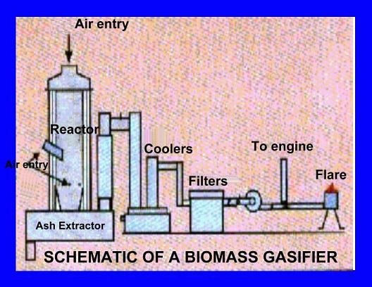
GASIFIER
REACTOR
The reactor is a cylindrical vessel made of mild
steel, with an inner lining of cold face insulation
bricks and ceramic tiles composed largely of alumina.
Air nozzles, provided around the combustion zone,
are kept open during the running of the system.
To allow for uniform air availability across the
reacting bed, an additional air nozzle called
the central nozzle is directed to the reactor
core. A water seal with a removable cover forms
the top of the reactor, which is kept open during
the entire operation of the system, to facilitate
primary air induction and loading of feedstock.
A grate is provided at the reactor bottom to hold
the char or ash as the case may be, with a mechanism
for intermittent extraction of char/ash.
GAS
COOLING SYSTEM
It consists of a direct water impingement cooler,
which is meant for cooling the hot gases from
the gasifier reactor to ambient for engine applications
and scrubbing the gas to remove the entrained
tar and particulate matter. When the gasifier
system is operated at the rated load, the system
requires 80 M3/Hr on a continuous basis for
a one MW rating. The coolers perform the twin
functions of cooling and cleaning the producer
gas.
GAS FILTERING SYSTEM
This sub system consists of a series of a quartz
based gas filter, a bag filter, a catalytic
converter and a fine quality paper filter. The
purpose of the filtering system is to reduce
the quantity of tar, particulate matter and
moisture in the gas to levels that are acceptable
for direct admission into gas engines.
BURNER
This is provided to check the initial quality
of the combustible gas as also for emergency
flaring.
INSTRUMENTATION & CONTROL AUTOMATION
The Instrumentation consists of automatic gas
flow meter and pressure indicators located on-line
to monitor the quantity and rate of gas production.
Instrumentation is also provided for monitoring
temperatures in the reactor, automatic retraction
of top cover, automatic start/stop of the bucket
elevator, automatic control of gas feed into
the engine and automatic char/ash extraction.
Relevant parameters such as system pressures
along the gas flow path, gas consumed by the
engine and operating parameters such as pressure,
temperature, etc are also displayed for operational
convenience.
CONTROLS & SAFETY FEATURES
The system shall be provided with the following
safety elements
1) Oxygen monitoring system - to indicate if
there is any leakage of air into the system,
forewarning the operator to take necessary preventive
action.
2) Water seals - most of the system elements
are provided with water seals to release pressure
in the event of the system getting pressurised.
The water seals, with their low-level bubbling
noise, also act as adjunct annunciators of system
pressure build-up.
3) Automatic reactor shut off - to shut off
the reactor automatically in the event of power
failure.
4) The automation for start-up consists of a
plc based control system, which controls the
following actions:
5) Automatic retraction of top cover with pneumatic
arms.
6) Automatic positioning of two-way chute.
7) Automatic cut-on and cut-off of biomass loading
in the reactor using ultrasonic sensors.
8) Automatic control of blower operation providing
secondary air to the reactor.
9) Automatic extraction of ash from the grate
bottom.
10) Automatic control of air blower speed to
suit engine requirements.
11) Automatic emergency flaring of gas.
12) Automatic emergency shutdown of reactor.
COMPUTERISED DATA ACQUISITION SYSTEM
The plant is provided with a computerised data
acquisition system to facilitate automation
and easy access to real-time operating parameters.
The following relevant data pertaining to systems
operation can be recorded and acquired on-line
on the computer:
1. 1. Reactor temperatures at different zones.
2. 2. Biomass consumption rate.
3. 3. Gas-flow rate.
4. 4. Technical trouble-shooting.
5. 5. Maintenance Schedule, both preventive
and breakdown.
6. 6. Technical manual.
AUXILIARIES
BIOMASS
SIZING SYSTEM
The plant should incorporate size reduction
unit for cutting the biomass into smaller pieces
prior to feeding into the gasifiers.
BIOMASS TRANSPORTATION SYSTEM
The biomass shall be transported with the help
of a front-end loader, which consists of a tractor
provided with front-loading articulated arms
fitted with loading bucket, for loading it onto
the hopper of the bucket elevator.
BIOMASS CONVEYING SYSTEM
Operation of the gasification plant requires
loading of biomass into the reactor in a continuous
batch wise basis. At full load of operation,
1000 kg/hr. system consumes biomass at the rate
of 1000 kg/hr. The Power Plant has a Bucket
Elevator of suitable capacity to facilitate
continuous loading of biomass into the two reactors
via two-way chute.
WATER
TREATMENT PLANT
As mentioned earlier cooling water is required
for cooling and scrubbing of the gas prior to
supply of gas to the engine. Cooling water of
about 80 M3/hour is required on a continuous
basis. To optimise on the utilization of limited
resources, the system will recycle the wash
water. The Power plant incorporates a Water
treatment Plant for continuous filtration and
purification of water.
COOLING
TOWER
A Cooling Tower is provided for cooling the
recycled cooling water, after water treatment,
to maintain its temperature within the prescribed
limits.
CHAR EXTRACTION UNIT
The system is provided with Char Extraction
Unit consisting of a screw blender for intermittent
extraction of char/ash. The coconut charcoal,
which has commercial value as an industrial
adsorbent, is milled to the required size, bagged
and sold.
PROJECT
REQUIREMENTS TO BE PROVIDED AS CLIENT'S SCOPE
OF SUPPLY
SITE
REQUIREMENTS FOR THE POWER PLANT
The
land required for a one MW power plant is 1
Acre. The land will have to be graded and leveled
and provided with main gate, perimeter fencing,
access roads, parking areas, security room and
cycle stand.
BUILDING REQUIREMENTS FOR THE POWER PLANT
The general requirements for Civil Buildings
(Client's Scope) for the Power Plant are as
follows: |
| The
estimate for machinery foundations is about
36 cubic meters. Other building services such
as sewerage and water connections, fire alarm
system and telecommunication facilities need
to be provided.
MISCELLANEOUS
ASSETS FOR THE POWER PLANT
The
Client has to make provisions for furniture
and fixtures, office equipment, canteen equipment,
safety & medical equipment, maintenance
workshop equipment, laboratory equipment housekeeping
equipment besides utilities such as bore well
and pump.
DETAILED
OFFER FOR 1000 KG/HR BIOMASS GASIFICATION PLANT
SCOPE OF WORK
The Scope of Work shall be Supply, Installation,
and Testing & Commissioning of 1000 kg/hr
Biomass Gasification Plant. The Scope of Work
shall generally be as under:
A. Supply & Installation
1. FABRICATION, SUPPLY & INSTALLATION OF
COMPLETE GASIFICATION PLANT CONSISTING OF
1.1 Gasifier Reactor 1000-kg/hr
1.2 Gas Cooling System
1.3 Gas Filtering System
1.4 Burner
1.5 Instrumentation
1.6 Controls & safety features
1.7 Computerised Data Acquisition System.
B. Testing & Commissioning
1. Testing & Commissioning of the complete
Gasification system to ensure that performance
guarantees and specifications are met.
C.
Performance Monitoring
1. Monitoring of performance for a period of
6 months after commissioning to ensure that
the Gasification Plant performs to specifications
for extended periods in grid connected mode.
CLIENT'S RESPONSIBILITIES
A. Land
1. Provision of land at Client's cost for setting
up the Gasification Plant.
B. Design & Detail Engineering
1. Design, detail engineering and construction
supervision of all components of the Project
other than the gasification plant such as civil,
mechanical and electrical including evacuation.
C. Civil Work
2. Execution at Client's cost of all Civil Work
connected with the Power Plant generally as
per our Plant Building Layout and detailed civil
drawings, such as Raw Material Storage Shed,
Gasification Plant Shed, & Effluent Treatment
basin etc.
D. Other Project Costs
1. Provision at Client's cost for expenditure
on other Project Costs such as Miscellaneous
Assets, Pre-operative Expenses, and Contingency
provisions, Working Capital Margins etc.
E. Clearances & Sanctions
1. Provision at Client's cost of all necessary
information to statutory and other authorities
and obtaining early clearance and approvals
without causing delays in project execution. |